|
|
Post by farmboy on May 7, 2020 17:39:25 GMT -6
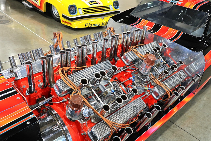
I'm looking for a schematic or even a simple box and line drawing of the cv (crankcase ventilation. Thank you Rocketeer) plumbing for the Tommy Ivo 4 engine Showboat, specifically from the GMP 1/18 diecast. This model has these lines. I have the Revell 1/25 Tommy Ivo Showboat kit and want to build and detail it but am having no luck finding any definite info on this plumbing aspect.. If anyone has a GMP 1/18 diecast (or could connect me with someone who does), and could draw a reliable diagram or schematic and get it to me, or, point me where to find this info it would be appreciated. I have the fuel line routing and throttle assembly more or less nailed down (I hope). Thanks for any assistance you may be able to provide. Would this build qualify as a showrod?
|
|
|
|
Post by rocketeer on May 7, 2020 23:35:36 GMT -6
What's "cv"?
|
|
|
|
Post by farmboy on May 8, 2020 3:32:22 GMT -6
Crankcase Ventilation. Sorry, I've since corrected that in the first post. I'm told it's that little line going in to the corner of the manifolds on all 4 engines. As there are no breathers on the valve covers, and no other visible hose off the front of the engines, plus the fact that's what I've been told it is lol I'd like to know how to plumb it.

The line I'm referring to can be seen on upper left of the manifolds on the bottom two engines, and bottom left on the two upper engines but how and where does it begin? There's an obvious tee, but in some photos it appears also to join to the fuel pump assembly (like a pcv valve from valve cover to air intake to reburn the air) from below but I wonder if it has a "catch can" for any excess oil that may burp. At last resort I will follow the above arrangement (as it's pretty detailed) and fudge something, however the engines are the focal point of the model and I'd like to simulate this line as close as I can. It's like trying to get a clear photo of a Sasquatch or Bigfoot lol. |
|
|
|
Post by rodsnracin on May 11, 2020 11:36:26 GMT -6
Can't help with the GMP schematic, but in studying pictures of the real thing, those lines look like they are plumbed into the water passages of the heads. I found one pic that showed the opposite end of one of the heads with a water temp gauge line into the same boss that those other lines are plumbed into. I "assume" they are air-bleed/pressure relief lines of some sort to let out excess air or steam as the engines heat up, not sure where they go to the rear, still looking! Might just outlet into a header pipe or the frame. HTH!
Brian
|
|
|
|
Post by 41chevy on May 11, 2020 12:21:47 GMT -6
Same chassis and engines in Ivo's Wagon Master. Here's a pic from the GNRS 2019.Coolant lines to heads and smaller coolant equalizer lines from right to left heads.  |
|
|
|
Post by farmboy on May 11, 2020 18:00:52 GMT -6
Wow, what a great place for help! Guess the crankcase ventilation theory goes out the window. The GMP is obviously a simplified representation and the one my buddy relied on. It made sense at the time. Any idea where this plumbing system begins or is it possibly a closed system? Thanks again for the eye openers guys, this is really great.
|
|
|
|
Post by 41chevy on May 12, 2020 13:23:36 GMT -6
Wow, what a great place for help! Guess the crankcase ventilation theory goes out the window. The GMP is obviously a simplified representation and the one my buddy relied on. It made sense at the time. Any idea where this plumbing system begins or is it possibly a closed system? Thanks again for the eye openers guys, this is really great. Here are some more pics. Shot of Black coolant tank right front, details of 3/8 fuel lines, a shot of short 1" chrome tubes running between engines for coolant and the smaller lines off the intake near the heads are steam bleeds for the coolant. The large chrome lines in the very first post between the engines are the main coolant feed lines to all four engines. and one of the Show Boat (left in photo) and Wagon master together. This should give you the fuel and coolant system views you need. Also notice the fuel pumps for the injectors are below the magnetos on the engines. I can dig more out
Attachments:
|
|
|
|
Post by farmboy on May 12, 2020 17:04:28 GMT -6
thanks for the info '41. The nest of lines is beginning to make more sense now. A couple of questions though. "Steam bleeds". That's new to me, where/how would they connect? Also, though I haven't been researching this car for very long, in reference pics I've been collecting I've always taken the black container on the right front to be the fuel cell as I've not seen another container on the frame. I took the aluminum box on the front of the original (later the Wagonmaster) last photo, to be for fuel. This is not my first rodeo but I'm quite out in left field for some of the plumbing on this kit. Thank you guys for all your help. I wouldn't be asking all these questions, but as I mentioned earlier, on this beast the engines ARE the model and I'm trying my best to get things sorted out before I begin the build.
|
|
|
|
Post by 41chevy on May 13, 2020 17:00:51 GMT -6
Look closely at the very first picture I posted on the Wagon Master at the GNRS, you will see a 1/4 inch steel line running from the left head to the right head passing behind the magneto. That is the steam bleed/ balance line at the very highest point of the engine. The black tank is the 2.5 gallon fuel tank the Big tank on the right chassis is a combo of fuel and coolant. There is a quart capacity water tank in the Hot Rod article from 1961 that was on the bottom of the fuel tank originally. I don't see it on my build photos. It was supposed to use the fuel to cool the water. It appears to be eliminated down the road.
|
|
|
|
Post by farmboy on May 14, 2020 3:46:39 GMT -6
Hey Paul. Much thanx for some incredibly elusive info, but I just found (yesterday) a link that answers about 99% of what I needed to know. Oddly I found it in the Jalopy Journal (H.A.M.B). There's a further link in the l o n g thread. www.scalemotorcars.com/forum/hot-rods-and-customs/138197-tommy-ivos-showboat-1-8-scale.html\Going to take a while to plan my build, maybe start in the fall. Thanks again for your input, it's well received. Would this oddball car qualify for a Coffin Corner build? Thanks again to everybody who helped with info and support for this one and the Revere Raider's Coach. |
|

