|
|
Post by Bud Tugly on Jun 21, 2014 15:09:56 GMT -6
Actually Ford flatties only had 3 exhaust ports per side so that's a few less pipes to deal with but it's still going to be a lot of plumbing. Maybe dragster style "zoomie" headers?
|
|
|
|
Post by scurvydklown on Jun 21, 2014 18:39:36 GMT -6
Yeah - I'd say six vertical-ish pipes straight up the center, and three horizontal zoomies out each side.
|
|
|
|
Post by hobbybobby on Jun 22, 2014 5:31:43 GMT -6
Thanks for the suggestions, and yes I already know that this type of motor has only six exhaust ports...  This design had the camshaft above the crankshaft, as in the later pushrod operated overhead-valve engine. Valves for each bank were mounted inside the triangular area formed by the "Vee" of cylinders. The intake manifold fed both banks from inside the Vee but the exhaust had to pass between the cylinders to reach the outboard exhaust manifolds...  The first thought was that maybe it looks kooler with eight...  But you are right, Dave, I'll spoil something in this kind, six vertical-ish pipes straight up the center, and three horizontal zoomies out each side... |
|
|
|
Post by hobbybobby on Jun 22, 2014 9:15:34 GMT -6
And, it goes on... I leave aside for the moment the engine, and devote myself to other things... Since I want to leave this vehicle fly very low, I have to change other parts... ... for example, the transmission, the transmission output, the suspension of the rear wheels and its drive and where the prop shaft will go through... For all these concerns I need to open the floor again, now in other places... As already mentioned, there is also here, no exact plan, first I make a mark area with a pen... 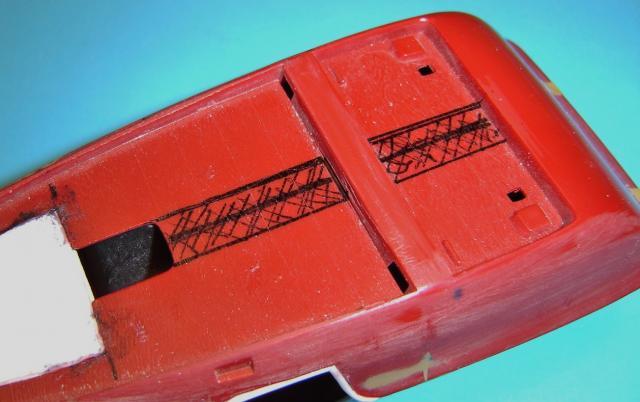 Then I remove it rough and refine the opening...  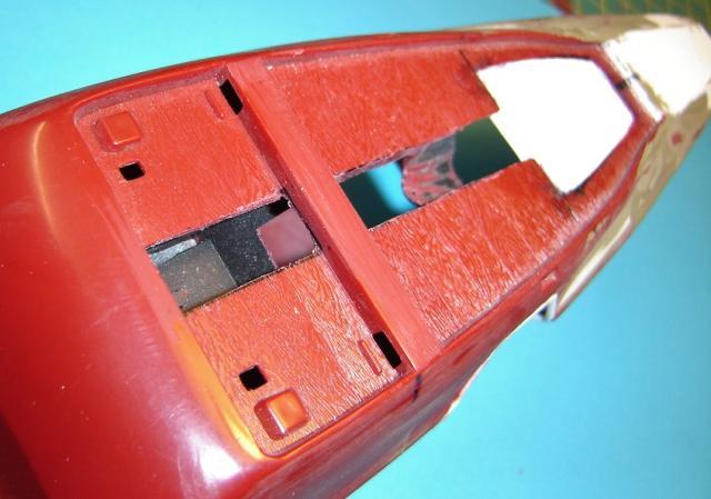 Thus, there is even in the interior some changes... 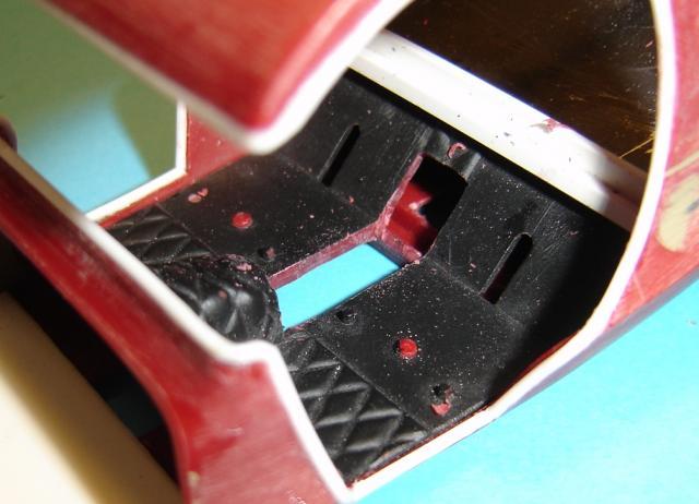 |
|
|
|
Post by scurvydklown on Jun 23, 2014 8:40:55 GMT -6
So, some kind of IRS tucked up in there? Corvette, Jaguar, or something more exotic?
|
|
|
|
Post by hobbybobby on Jun 26, 2014 14:04:25 GMT -6
Many vehicles have an IRS, as the name implies, a Independent Rear Suspension has the rear wheels independently sprung. A fully independent suspension has an independent suspension on all wheels. Some early independent systems used swing axles, but modern systems use Chapman or MacPherson struts, trailing arms, multilink, or wishbones. Independent suspension typically offers better ride quality and handling characteristics, due to lower unsprung weight and the ability of each wheel to address the road undisturbed by activities of the other wheel on the vehicle. Independent suspension requires additional engineering effort and expense in development versus a beam or live axle Arrangement, a very complex IRS solution can also result in higher manufacturing costs. The key reason for lower unsprung weight relative to a live axle design is that, for driven wheels, the differential unit does not form part of the unsprung elements of the suspension system. Instead it is either bolted directly to the vehicle's chassis or more commonly to a subframe. The relative movement between the wheels and the differential is achieved through the use of swinging driveshafts connected via universal (U) joints, analogous to the constant-velocity (CV) joints used in front wheel drive vehicles. Well, Dave, I've been thinking about, but I have nothing suitable at Hand and the lack of space does not Permit, that I could squeeze in here something Elaborately... Hmm... Actually, I wanted to just look out the differential, follows I made this hole with a conical reamer 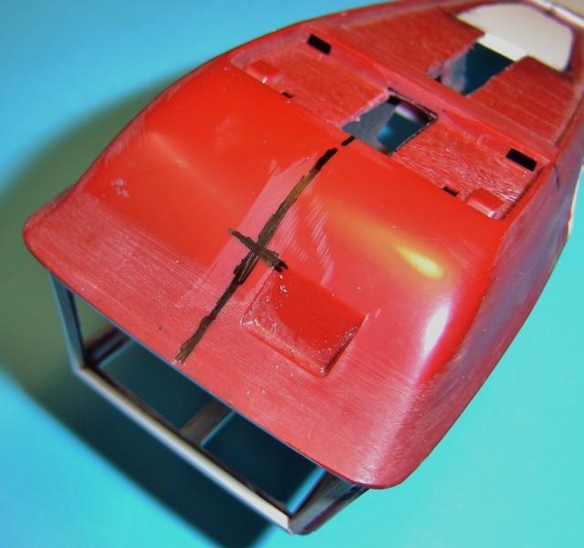  I wanted to have a straight bore as possible to the engine compartment... 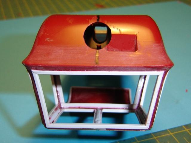 But somehow you're right, that would be too easy...  So, I saw out a recess, for the beginning... 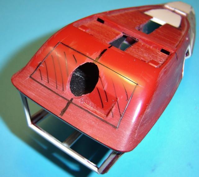  |
|
|
|
Post by scurvydklown on Jun 26, 2014 14:24:59 GMT -6
Hmmmmm...interesting.
|
|
|
|
Post by hobbybobby on Jun 30, 2014 17:17:20 GMT -6
Hmm... I have spent a long time with the interplay of many parts, for an IRS, but now I'm stuck...  I leave aside for the moment the rear drive and suspension and devote myself to other things... In the interior has emerged a hole now, by the intervention, in order to lay up the drive shaft... To fill this up with something appropriate, I have found this: 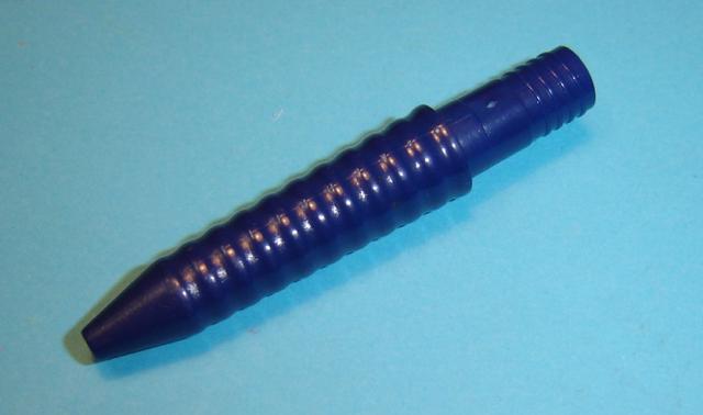 This is the front part of a ballpoint pen, from which I cut this Segment: 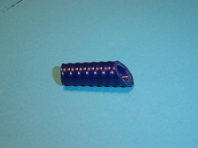 A first test, inserted between the seats:  And secondly, all the components in place: 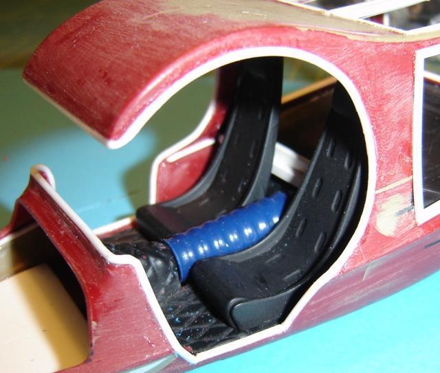 |
|
|
|
Post by hobbybobby on Jul 2, 2014 16:21:02 GMT -6
And, it goes on... I have made to the transverse grooves, additional longitudinal grooves... 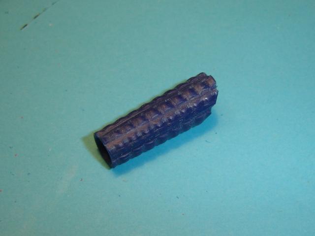 ... again a small test fit...  The round version still reveals some gaps in the lower range... ... that's why I first made an incision from below, after that I warmed the lower sides and have bent them outwards, to a U...  ... and so, it looks finished now, in terms of the shaping...   ... and the final test fit... 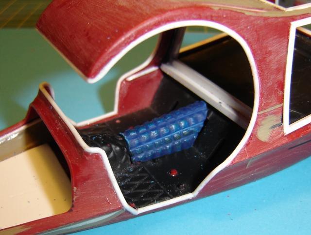 |
|
|
|
Post by scurvydklown on Jul 10, 2014 18:15:41 GMT -6
Great work, Bobby!
|
|
|
|
Post by hobbybobby on Jul 25, 2014 16:06:35 GMT -6
Thank you, Dave!  Smal steps... I have refined the front a little and then applied again some putty,,,  ... and the same from below... 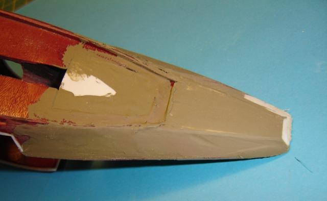 I have thought about the rear axle, but have not yet come so far now, the marked crosses show the center of the rear wheels, let's see what will happen...  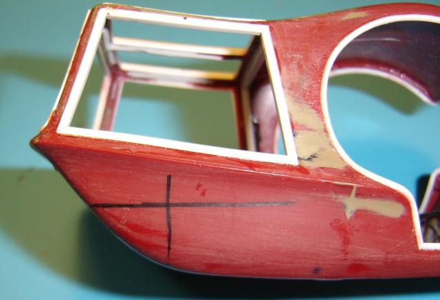 |
|
|
|
Post by Brandon on Apr 19, 2017 8:34:28 GMT -6
oooooohhhhh that's cool !
Love the ballpoint pen hack, too. Great idea.
|
|
|
|
Post by kabdriver on Apr 29, 2017 10:56:46 GMT -6
oooooohhhhh that's cool ! Love the ballpoint pen hack, too. Great idea. Me too! It takes a real artist to see household objects like that and think "hey, a trans tunnel!" |
|
|
|
Post by hobbybobby on Aug 17, 2017 17:28:52 GMT -6
Thank you very much for the kind words!  This thread has its pictures again... |
|
|
|
Post by kabdriver on Aug 17, 2017 20:29:02 GMT -6
I've gotta say Bobby - I'm REALLY glad you've been restoring these posts. It's like getting to see a bunch of new builds all at once! So inspiring!
|
|
|
|
Post by hobbybobby on Feb 26, 2018 12:13:11 GMT -6
Thank you very much for the kind words, Jim!  |
|
|
|
Post by hobbybobby on Feb 26, 2018 12:23:29 GMT -6
|
|
|
|
Post by hobbybobby on Feb 26, 2018 12:27:58 GMT -6
Now I'm not sure anymore about the look of this front, hmm... 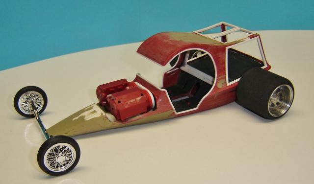 Any ideas and suggestions? |
|
|
|
Post by kabdriver on Feb 26, 2018 18:14:55 GMT -6
I think it looks great so far! Some nice linkages from the front axle running back to the body where the front or back of the engine is would really bring the front together maybe? But what do I know, you're better at this than me  |
|
|
|
Post by "ScratchFever" on Feb 26, 2018 20:05:55 GMT -6
Looking good HobbyBobby... Really
|
|
|
|
Post by 41chevy on Feb 26, 2018 21:58:24 GMT -6
Extremely nice. The steering link, radius rods and exhaust headers will set it off in think. Paul
|
|
|
|
Post by "ScratchFever" on Feb 26, 2018 22:19:37 GMT -6
Bobby glad your getting back to finishing these builds bro.. It's really inspiring.. Just love your work.. Rock on bro.. I'm thinking the front end to maybe just dragster it out... Or maybe changing the nose to a more blunt effect.. Thanks for the eye candy
|
|
|
|
Post by davemarek on Feb 27, 2018 20:12:47 GMT -6
|
|
|
|
Post by kabdriver on Feb 27, 2018 20:56:29 GMT -6
Yes!!! Just what I was thinking! That helps the nose SO much!
|
|
|
|
Post by davemarek on Feb 27, 2018 22:05:30 GMT -6
Bobby/Kab
Moved the rear wheel forward a small amount as well just to give it a different stance
|
|
|
|
Post by "ScratchFever" on Feb 28, 2018 0:16:27 GMT -6
The front end was what I was getting at stating a more blunt effect.. With dragstering out... Sweet!
|
|
|
|
Post by chromecop on Feb 28, 2018 8:14:09 GMT -6
I agree to this idea!!! The shorter nose givs a totally different approach to the car! |
|
|
|
Post by patw on Mar 14, 2018 3:04:03 GMT -6
Looks superb so far, keep going!
|
|
|
|
Post by 30woody on Apr 17, 2018 15:24:55 GMT -6
looks fantastic Boban...I agree with Pat-- Keep going!!!
|
|
|
|
Post by hobbybobby on Oct 28, 2018 18:29:20 GMT -6
Thank you very much for the kind words!  Have played around a little and tried a few things, that's what came out. This is the original axle of the Pie Wagon:  Drilled out the hole...  ... for the matching inox tube...  ... together it looks like this...  |
|

